Controlled microfluidic reagent dissolution via capillarity

Controlled microfluidic reagent dissolution via capillarity

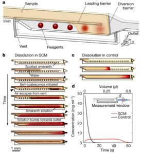
Fig 2 Onur Gökçe at University of Zurich/ETH and Yuksel Temiz and Emmanuel Delamarche at IBM in Zurich, Switzerland, together with Samuel Castonguay and Thomas Gervais at École Polytechnique in Montréal, Canada recently authored a clever article in Nature that shows beautiful control of dried reagent dissolution and diffusion into the liquid buffer flowing over-top of the reagents in a microfluidic channel.

The authors demonstrated that, by including a partial-height longitudinal wall to act as a “capillary pinning line”, liquid flows through an empty channel and back along the adjoining channel with spotted reagents to create zones of dissolved reagents – a process they term ‘self-coalescing flow’ or SCM.  This is in contrast with the frontal accumulation of  reagents spotted conventionally along a single channel.  Further, by adjusting channel dimension, the concentration profiles could easily be manipulated to produce short zones of high-concentration or longer zones of lower concentration, with fairly homogeneous concentration profiles in all cases.  Several additional examples showed the ability to either segregate or coalesce such zones for a given reagent, mix and react with downstream reagents, etc.
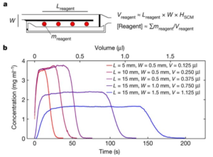
Fig 3From the perspective of microfluidic product development, this development is very interesting for several reasons.  First, it provides this control of reagents in solution with very simple channel structures that can be fabricated existing standard methods for any substrate material (plastic, glass, silicon).  Secondly, it may obviate the need for more complex channel networks and associated pumps and valves required to physically segregate parallel reactions of a single analyte with several target reagents for multiplexed analyses, common in many microfluidic products currently.  This could reduce the size, complexity and cost of the chip consumable, making the price and profitability of such products much more attractive.

Stabilisation of hydrogen peroxide on paper microfluidics with poly(vinyl alcohol)

Stabilisation of hydrogen peroxide on paper microfluidics with poly(vinyl alcohol)

printed spotsResearchers from Wanida Wonsawat‘s group at Suan Sunandha Rajabhat University (Bangkok) and Takashi Kaneta‘s group at Okayama University recently published an article in Nature Research showing a relatively simple but elegant procedure to greatly increase the stability of hydrogen peroxide reagent absorbed into the fibres of the patterned Whatman filtre paper used the paper microfluidic devices in the study.  Hydrogen peroxide is an oxidising agent that is often used in enzymatic assays that may create or remove a separate species that can be measured via indirect optical detection using colourimetry, fluorescence, chemiluminescence, etc.

The paper microfluidic devices (or paper-based analytical devices, PADs) were created by with a commercial wax printer, and the exposed paper areas were treated  with the colourimetric reagents.  For these trials, simple circular areas were patterned for the proof-of-principle studies undertaken, in lieu of channel networks.  The reagents used were 3, 3′, 5, 5′-tetramethylbenzidine (TMB, the substrate and also colourimetric reagent), bovine serum albumin (BSA), phosphate buffer and hydrogen peroxide, with or without the poly(vinyl alcohol) (PVA).  Horseradish peroxidase (HRP, the enzyme ) was contained in the sample solution.  TMB changes to blue in the presence of HRP and hydrogen peroxide.

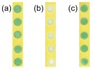
The authors discovered that blue colour seen upon initial reaction faded after a day, and isolated the cause to decomposition of the hydrogen peroxide on the PAD during this time.  The figure above shows PADs with the enzymatic assay occurring in the patterned dots, where a) both hydrogen peroxide and TMB were added to the PAD, and the results are captured shortly after reaction; or the PAD with only b) hydrogen peroxide or c) TMB is prepared and stored at room temperature for one day, and then the other reagents are added and the results captured.  Degradation of the hydrogen peroxide causes the near total loss of signal in b).

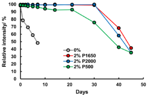
extended refrigerated lifetimesTo stabilise the hydrogen peroxide, they added PVA to the hydrogen peroxide solutions prior to addition to the PAD, and found dramatic improvements in hydrogen peroxide stability.  The extent of the improvement varying with PVA concentration and chain length, as well as storage temperature.  2% solutions of PVA with a length of ~1650 monomers extended the life of the reaction at ~100 intensity to 10 days with storage at room temperature, while refrigeration at 4°C extended that to 30 days for PVA lengths of ~1650 or 2000 monomers.  The PVA is thought to protect the hydrogen peroxide by forming a liquid- and air-tight barrier, thus preventing attack by hydroxide anion that catalyses the degradation.
The importance of extending reagent lifetimes in microfluidic devices is a critical building block for the development of point-of-care/use devices.  In this case, isolation and stabilisation of the hydrogen peroxide reagent, in widespread use for enzymatic assays, is of obvious benefit.  30 days of refrigerated storage is much better than a few hours, but a long way from the requirements for a robust product with a minimum 6-month shelf-life.  However, one could imagine product development efforts with currently available packaging technology, e.g. desiccation followed by vacuum packaging or dry inert gas packaging, might easily eliminate the moisture-catalysed degradation, and thus extend product life significantly.  There are also other stabilising polymers to choose from that may be better optimised for other types of reagents requiring a liquid/gas barrier.


Wood microfluidics devices

Wood microfluidics devices

device-arrayI guess it’s not a big stretch to go from paper to wood for microfluidic substrates, but I’m impressed nonetheless!  Govind Rao‘s group in Chemical Engineering at the University Maryland recently published an ASAP article in Analytical Chemistry (alternatively use this DOI) about microfluidic devices made in plywood.

The Rao group machined channels and features in 35 chips laid out on 12″ x 12″ plywood sheets using a CO2 laser printer.  Devices were treated with a 0.1-1% PMMA or Teflon solution to seal up pores and inhibit capilarity which would otherwise promote seepage of sample and running buffers in the substrate.  Wooden channel layer substrate was bonded with cyanoacrylate glue to wooden cover plate with through-holes accommodating Luer lock fittings; PMMA covers were sometimes used for visualisation.  Channels were ~0.68 mm-deep X 1 mm-wide, and the system tolerated pressures of ~2 psi.  Different laser rastering speeds and line thicknesses were explored.  Identical devices were made out of PMMA for performance comparison purposes.

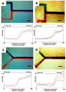
t-and-y-mixerRuns with blue and red food dye mixed at Y- and T-intersection mixers were performed and imaged to compare performance in a simple flow experiment.  The figure at right shows comparable performance (PMMA in left column, wood in right column), though for both geometries, the wood chips do not provide an even amount of the two dyes (less red dye), and the signal is noisier, as shown by the black standard deviation lines above and below the red average signal lines.  No discussion was found concerning these two discrepancies.
The authors discuss the biodegradable advantage that wooden devices have vs. their polymer or glass counterparts, and how this is becoming increasingly important with new legislation banning single-use plastics coming into force in many jurisdictions.

Open channel microfluidics

Open channel microfluidics

theberge-open-chnl-uf-1An interesting article from Ashleigh Théberge’s group at the University of Washington reviews the relatively recent introduction of open capillary microfluidic systems (as distinct from electrowetted digital microfluidics).  The paper was recently pre-published in Analytical Chemistry as an ASAP article.

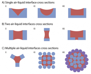
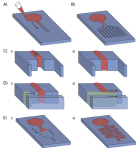
theberge-open-chnl-uf-2The authors review a number of different channel geometries and fibre bundle configurations that can be used to promote open capillary flow.  The helpfully provide the equations that use channel geometry and contact angle to determine whether capillary flow is energetically favourable.  This is done for both conventional monolithic (single material) channels, as well as composite material channels.
Pros and cons of the open capillary approach are surveyed.  The authors list several advantages:

  1. simplified fabrication by obviating the need for bonding and potential associated use of solvents on the substrate, process development/trade secrets, manufacturing cost, etc.;
  2. ease of performing surface modifications, such as for hydrophilicity/hydrophobicity, silanisation or other derivitisation, blanket or patterned exposure to UV, plasmas, chemical or physical vapour depositions (PVD & CVD), application of delicate bio-reagents that can’t withstand thermal bonding;
  3. accessibility of channels for adding or removing reagents or components with pipettes, tweezers (as for tissue scaffolds)
  4. elimination of air bubble issues, due to the open interface.

They also mention disadvantages primarily stemming from the open channel access such as higher evaporation, evolution and/or exchange of dissolved gases, liquid leaks to non-channel paths, and the inability to generate higher pressures in channels (beyond those of capillarity) and thus use valves, etc.

Lastly, a number of different applications are noted, though all appear to be academic in nature at this stage.  While I see the advantages of flexibility and reduced manufacturing cost offered by the open channel concept, I wonder how a product would be able to mitigate against evaporation and contamination issues in viable approach suitable for a robust consumable suitable for untrained users.  Perhaps the authors have the answers; they mention that they have financial interests in two companies, Salus Discovery and Stacks to the Future, involved in the commercialisation and IP related to some of the technologies presented.

Dendrite cell chemotaxis in microfluidic mazes

Dendrite cell chemotaxis in microfluidic mazes

korean-chemotaxis

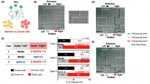
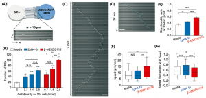
South Korean researchers have recently shown that immature dendrite cells undergo chemotactic migration through microfluidic mazes preferentially towards healthy or cancerous cells versus cell-free medium.  The new research findings, published in a Lab on a Chip article, come from Cho’s group at the Institute for Basic Science, Grybowski’s group at the Ulsan National Institute of Science and Technology, and Jeon’s group at the Pohang University of Science and Technology.

Chemotaxis is the movement of cells towards or away from chemical stimulus (attractants or repellents, respectively).  Bacteria accomplish this through biased ‘random’ walk cycles, where the cells use their flagella to move in a given direction, then stop and sense whether they have moved up or down the stimulant’s concentration gradient to determine subsequent reorientation and straight-line translation.  Migration towards attractants by dendrite cells (surveillance agents and messengers for the immune system) is well documented for mature but not immature dendrite cells.

In this study, immature cells were allowed to migrate towards cell medium (control), EpH4-Ev healthy cells or beta-MEKDD 116 cancer cells.  In one experiment series, comparisons in migration were evaluated by allowing the immature dendrite cells to migrate from a single inlet towards either of two outlets that contained two of the three cell attractants.  Attraction bias was clearly shown to be (beta-MEKDD 116) > (EpH4-Ev) > (cell medium).  In another series of experiments, different cytokines drawn from the cancerous beta-MEKDD 116 cells were compared, and the protein Gas6 was found to have the largest attractive effect.  Large numbers of replicate analyses allowed the authors to nicely quantify the confidence limits that applied to their results.korean-chemotaxis2


First image of black hole: epitome of scientific collaboration

First image of black hole: epitome of scientific collaboration

black-hole-different-observatories Accomplishements in microfluidics and analytical chemistry are normally front and centre in this blog, but this is a nod to some great work in physics.  It turns out physics is more complicated than F = ma. 😉

There was a big splash in the media around April 10th about the first images of a black hole ever obtained, and they are indeed pretty fascinating.  What is at least as fascinating is the coordinated, collaborative effort between the astrophysics teams in several countries to generate these images.  A few editorial pieces summarise the tremendous scope of the work nicely on webpages at MIT, the Event Horizon Telescope (or EHT), and publisher IOP.  There are six open-access publications listed at the bottom of the EHT page that describe the work and its results.

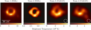
The teams all belong to the EHT which is an array of radiofrequency telescopes that work in harmony to image a given target at the same time.  The resolution afforded by teaming the individual telescopes together is vastly better than that of any individual telescope.  A few images from papers that were published simultaneously on April 10 show some of the results.  The first shows several pictures of the M87 black hole taken from different observatories early in the project, before many of the efforts at noise reduction were implemented (image from Figure 4 of this paper).  array-of-different-observatoriesThe second shows the location of the different observatories in Europe, North and South America, Hawaii and Antarctica that were teamed together for the effort (image from Figure 1 of this paper).

To be able to work synchronously, all the observatories had to use precise timestamping of their images with atomic clocks.  Each observatory generated so much data, about 1 PB (PB = petabyte = 1 million GB), that it was faster to simply fly the hard drives to the Max Planck Institute for Radio Astronomy (Germany) and MIT’s Haystack Observatory (Boston, US) for the data processing.  Interestingly, the images black-hole-different-dayschange appreciably from day to day, as shown below (image from figure 15 of this paper).
Any collaborative scientific effort of this size is remarkable, all the more so given the size of the groups in different countries, funding sources from yet many more countries, etc.


Microfluidic microneedle PoC system created by laser machining

Microfluidic microneedle PoC system created by laser machining

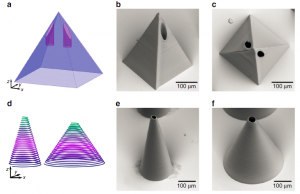
german-microneedlesA recent article in Nature: Microsystems & Nanoengineering by Ralf Hellmann’s group at the Aschaffenburg University of Applied Sciences and Thomas Walther’s group at the Technische Universität Darmstadt in Germany outlines impressive laser machined microfluidic microneedle devices.

Devices were fabricated in PMMA coated in OrmoComp® photoresist in a two-step process.  Direct laser written photoresist microneedle arrays (tip radius of 13-21 µm) and 3-D microfluidic PMMA channels were combined in a device using a single femtosecond pulsed laser for fabrication.  The fabrication process is claimed to be simpler than traditional fabrication methods, but unfortunately, no throughput figures were provided.  It would be nice to know what these are to understand how readily this fabrication technique could be applied as a manufacturing tool.

Devices were characterised with force vs. time curves for injections of a rhodamine B test solution through pork skin (which shares similar morphology to human skin) and to verify microneedle integrity during use.

The authors highlight that the devices could provide a significant leap forward for point-of-care applications including drug delivery and diagnostics.

Microfluidic screening of bacteria for power generation, waste digestion

Microfluidic screening of bacteria for power generation, waste digestion

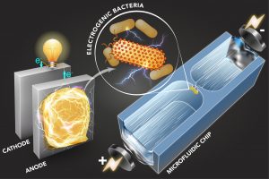
mit-electric-bacteria-pressNew research out of Cullen Buie‘s lab at MIT’s LEMI lab shows effective sorting of different strains of bacteria using microfluidics-based dielectrophoretic (DEP) analysis.  The research was published in Science Advances article (DOI: 10.1126/sciadv.aat5664) and also profiled by MIT News; a second MIT news article provides some background to microbial digestion and power generation.

The cell manipulation works by virtue of a DEP trap. A cell suspension flows through a small orifice (~ 50 µm wide) between two microfluidic chambers under an electric field.  The electroosmotic and electrophoretic forces generated by the field determine each cell’s speed in the bulk solution.  At the constriction, there is additionally a dielectrophoretic force that acts to trap cells of a certain polarisability, depending on the applied field strength.  Since polarisability relates to extracellular electron transfer (EET), or a cell’s tendency to generate electricity during respiration, the trap can act as a filtre or screen for bacterial strains based on their tendency to generate electricity.  In other words, different strains can be selectively trapped or screened based on the applied voltage.

The value of being able to discern between the different strains of bacterial in terms of their tendency to generate power while digesting the components in wastewater can hardly be understated.  Apparently 3 of energy in the US is spent on wastewater treatment, while the wastewater itself contains 10 times the energy required for its own processing.